PHILIPS CONSUMER ELECTRONICS, CO.
P2230 CE
|
Processor |
80286 |
|
Processor Speed |
8/12MHz |
|
Chip Set |
Unidentified |
|
Max. Onboard DRAM |
4MB |
|
Cache |
None |
|
BIOS |
Unidentified |
|
Dimensions |
254mm x 218mm |
|
I/O Options |
None |
|
NPU Options |
80287 |
|
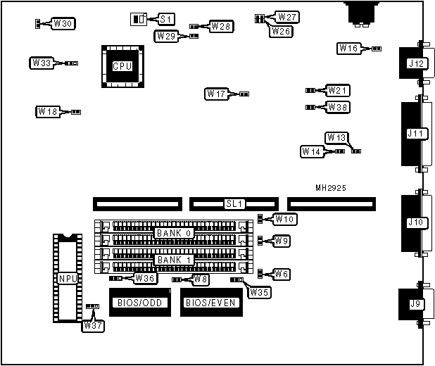
CONNECTIONS | |||
|
Purpose |
Location |
Purpose |
Location |
|
Serial port 1 |
J9 |
VGA port |
J12 |
|
Serial port 2 |
J10 |
Riser Card |
SL1 |
|
Parallel port |
J11 | ||
|
USER CONFIGURABLE SETTINGS | |||
|
Function |
Jumper |
Position | |
|
� |
SIMM size select 256K x 9 |
W6 |
Open |
|
SIMM size select 1M x 9 |
W6 |
Closed | |
|
� |
BIOS type select 27256 |
W8 |
Closed |
|
BIOS type select 27128 |
W8 |
Open | |
|
� |
RAM split select 384K above 1MB for EMS or extended |
W9 |
Open |
|
RAM split select 384K below 1MB for EMS or extended |
W9 |
Closed | |
|
� |
Burn in mode not active |
W26 |
Open |
|
Burn in mode active |
W26 |
Closed | |
|
� |
Manufacturing mode not active |
W27 |
Open |
|
Manufacturing mode active |
W27 |
Closed | |
|
� |
Floppy drive interface enabled |
W28 |
Open |
|
Floppy drive interface disabled |
W28 |
Closed | |
|
� |
Video type select normal |
W29 |
Open |
|
Video type select slow |
W29 |
Closed | |
|
� |
Speaker volume select low |
W30 |
Closed |
|
Speaker volume select high |
W30 |
Open | |
|
� |
I/O bus speed select 8MHz |
W33 |
Open |
|
I/O bus speed select 12MHz |
W33 |
pins 2 & 3 closed | |
|
� |
Factory configured - do not alter |
W38 |
Closed |
|
DRAM CONFIGURATION | ||
|
Size |
Bank 0 |
Bank 1 |
|
512KB |
(2) 256K x 9 |
NONE |
|
640KB |
(2) 256K x 9 |
(2) 64K x 9 |
|
1MB |
(2) 256K x 9 |
(2) 256K x 9 |
|
2MB |
(2) 1M x 9 |
NONE |
|
4MB |
(2) 1M x 9 |
(2) 1M x 9 |
|
DRAM SPEED CONFIGURATION | ||
|
Size |
W13 |
W14 |
|
100ns |
Open |
Closed |
|
120ns |
Closed |
Open |
|
DRAM JUMPER CONFIGURATION | |||
|
Banks used |
W16 |
W17 |
W18 |
|
1 |
Open |
Open |
Open |
|
2 |
Open |
Closed |
Open |
|
DRAM STROBE ADDRESS CONFIGURATION | |
|
Setting |
W37 |
|
SIMM U16 = Bank 1 column address strobe |
pins 1 & 2 closed |
|
SIMM U16 = Bank 2 column address strobe |
pins 2 & 3 closed |
|
SIMM U16 = address strobe not connected |
Open |
|
Note: On the diagram, U16 & U17 are shown as Bank 1. | |
|
DRAM STROBE ADDRESS CONFIGURATION | |
|
Setting |
W36 |
|
SIMM U17 = Bank 1 column address strobe |
pins 1 & 2 closed |
|
SIMM U17 = Bank 2 column address strobe |
pins 2 & 3 closed |
|
SIMM U17 = address strobe not connected |
Open |
|
Note: On the diagram, U16 & U17 are shown as Bank 1. | |
|
DRAM STROBE ADDRESS CONFIGURATION | |
|
Setting |
W35 |
|
SIMM U16 & U17 = Bank 1 column address strobe |
pins 1 & 2 closed |
|
SIMM U16 & U17 = Bank 2 column address strobe |
pins 2 & 3 closed |
|
SIMM U16 & U17 = address strobe not connected |
Open |
|
Note: On the diagram, U16 & U17 are shown as Bank 1. | |
|
ON BOARD VIDEO CONFIGURATION | ||
|
Setting |
W10 |
W21 |
|
Enabled |
Closed |
Closed |
|
Disabled |
Open |
Open |
|
VIDEO CONFIGURATION | ||
|
Setting |
S1/1 |
S1/2 |
|
Monochrome |
On |
Off |
|
Color |
Off |
On |