TYAN COMPUTER
S1366
|
Data bus: |
32-bit PCI |
|
Size: |
Half-length, full-height card |
|
Hard drive supported: |
Two IDE (AT) Interface drives |
|
Floppy drives supported: |
Two 360KB, 720KB, 1.2MB, or 1.44MB drives |
|
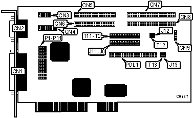
CONNECTIONS | |
|
Function |
Location |
|
25 pin parallel port - external |
CN1 |
|
9 pin serial port - external |
CN2 |
|
10 pin serial port - internal |
CN3 |
|
16 pin game port - internal |
CN4 |
|
34 pin data cable connector - primary floppy drive interface |
CN5 |
|
34 pin data cable connector - secondary floppy drive interface |
CN6 |
|
40 pin connector - primary IDE(AT) interface |
CN7 |
|
40 pin connector - secondary IDE(AT) interface |
CN8 |
|
4 pin connector - drive active LED |
CN9 |
|
S136x paddle card daughterboard connector |
PDL1 |
|
USER CONFIGURABLE SETTINGS | ||
|
Function |
Location |
Setting |
|
� Factory configured - do not alter |
J0 |
N/A |
|
� Floppy drive interface DSKCHG signal not intercepted |
J1 |
Open |
|
Floppy drive interface DSKCHG signal intercepted |
J1 |
Closed |
|
� I/O address fixed |
J2 |
Closed |
|
I/O address relocatable |
J2 |
Open |
|
� Primary IDE(AT) channel legacy IRQ tied to IRQ14 |
J5 |
Closed |
|
No primary IDE(AT) channel legacy IRQ tied to IRQ14 |
J5 |
Open |
|
� Primary IDE(AT) legacy ISA IRQ14 not buffered |
J6 |
Open |
|
Primary IDE(AT) legacy ISA IRQ14 buffered |
J6 |
Closed |
|
� Secondary IDE(AT) channel legacy IRQ tied to IRQ15 |
J7 |
Closed |
|
No secondary IDE(AT) channel legacy IRQ tied to IRQ15 |
J7 |
Open |
|
� Secondary IDE(AT) legacy ISA IRQ15 not buffered |
J8 |
Open |
|
Secondary IDE(AT) legacy ISA IRQ15 buffered |
J8 |
Closed |
|
� IDE(AT) interrupt native mode not utilized |
J9 |
Open |
|
IDE(AT) interrupt native mode utilized to PCI INTA |
J9 |
Closed |
|
� Factory configured - do not alter |
J10 |
N/A |
|
� AT printer mode(ISA) enabled |
J11 |
Open |
|
Normal mode enabled, floppy drive interface pin 29 grounded |
J11 |
Closed |
|
� Floppy drive interface normal DRATE out mode select |
P1 |
Pins 2 & 3 closed |
|
Floppy drive interface media ID input OS2 enhanced mode |
P1 |
Pins 1 & 2 closed |
|
� Floppy drive interface I/O address 3F0h select |
P2 |
Pins 2 & 3 closed |
|
Floppy drive interface I/O address 370h select |
P2 |
Pins 1 & 2 closed |
|
� Floppy drive interface enabled |
P3 |
Pins 2 & 3 closed |
|
Floppy drive interface disabled |
P3 |
Pins 1 & 2 closed |
|
� Factory configured - do not alter |
T0 |
N/A |
|
� ISA AT printer mode enabled |
T1 |
Open |
|
PS/2 bi-directional printer mode enabled |
T1 |
Closed |
|
� Parallel port interrupt IRQ7 select |
T2 |
Closed |
|
Parallel port interrupt disabled |
T2 |
Open |
|
� Serial port 1 interrupt IRQ4 select |
T4 |
Closed |
|
Serial port 1 interrupt disabled |
T4 |
Open |
|
� Serial port 2 interrupt IRQ3 select |
T5 |
Closed |
|
Serial port 2 interrupt disabled |
T5 |
Open |
|
� Game port enabled |
T6 |
Closed |
|
Game port disabled |
T6 |
Open |
|
PCI IDE CONFIGURATION | ||
|
Setting |
J3 |
J4 |
|
� PCI IDE channels enabled |
Closed |
Open |
|
PCI IDE channels disabled |
Open |
Closed |
|
SECONDARY IDE PCI INTERRUPT CONFIGURATION | ||
|
Setting |
J12 |
J13 |
|
� Secondary IDE interrupt not inverted(PCI bus INTB#) |
Open |
N/A |
|
Secondary IDE interrupt inverted(PCI bus INTB#) |
N/A |
Closed |
|
PRIMARY IDE PCI INTERRUPT CONFIGURATION | ||
|
Setting |
T12 |
T13 |
|
� Primary IDE interrupt not inverted(PCI bus INTA#) |
Open |
N/A |
|
Primary IDE interrupt inverted(PCI bus INTA#) |
N/A |
Closed |
|
PARALLEL PORT I/O ADRESS SELECT | ||
|
Address |
P8 |
P9 |
|
� 378-37Fh |
Pins 2 & 3 closed |
Pins 2 & 3 closed |
|
278-27Fh |
Pins 2 & 3 closed |
Pins 1 & 2 closed |
|
3BC-3BEh |
Pins 1 & 2 closed |
Pins 1 & 2 closed |
|
Disabled |
Pins 1 & 2 closed |
Pins 2 & 3 closed |
|
PRIMARY SERIAL PORT I/O ADRESS SELECT | ||
|
Address |
P4 |
P5 |
|
� 3F8h (COM1) |
Pins 2 & 3 closed |
Pins 2 & 3 closed |
|
2F8h (COM2) |
Pins 2 & 3 closed |
Pins 1 & 2 closed |
|
3E8h (COM3) |
Pins 1 & 2 closed |
Pins 2 & 3 closed |
|
Disabled |
Pins 1 & 2 closed |
Pins 1 & 2 closed |
|
SECONDARY SERIAL PORT I/O ADRESS SELECT | ||
|
Address |
P6 |
P7 |
|
� 2F8h (COM2) |
Pins 2 & 3 closed |
Pins 2 & 3 closed |
|
2E8h (COM4) |
Pins 1 & 2 closed |
Pins 2 & 3 closed |
|
3F8h (COM1) |
Pins 2 & 3 closed |
Pins 1 & 2 closed |
|
Disabled |
Pins 1 & 2 closed |
Pins 1 & 2 closed |
|
PARALLEL PORT INTERRUPT SELECT | ||
|
IRQ |
T2 |
T3 |
|
� IRQ7 |
Closed |
Open |
|
IRQ5 |
Open |
Closed |
|
Disabled |
Open |
Open |
|
ENHANCED PARALLEL PORT MODE CONFIGURATION | ||
|
Modes Supported |
P10 |
P11 |
|
� PRN |
Pins 2 & 3 closed |
Pins 2 & 3 closed |
|
PRN, EPP |
Pins 1 & 2 closed |
Pins 2 & 3 closed |
|
PRN, ECP |
Pins 2 & 3 closed |
Pins 1 & 2 closed |
|
PRN, ECP, EPP |
Pins 1 & 2 closed |
Pins 1 & 2 closed |
|
ECP MODE CONFIGURATION | |||||
|
Setting |
T7 |
T8 |
T9 |
T10 |
T11 |
|
� ECP mode disabled |
Open |
Open |
Open |
Open |
Open |
|
ECP mode w/DMA1 |
Closed |
Open |
Closed |
Open |
Closed |
|
ECP mode w/DMA3 |
Open |
Closed |
Open |
Closed |
Closed |
|
SERIAL PORT INTERRUPT SELECT | ||||
|
Port 1 |
Port 2 |
T3 |
T4 |
T5 |
|
IRQ4 |
IRQ3 |
open |
closed |
closed |
|
IRQ4 |
Disabled |
open |
closed |
open |
|
Disabled |
IRQ3 |
open |
open |
closed |
|
IRQ3 |
IRQ4 |
open |
T4 pin 1 to T5 pin 1 | |
|
|
|
|
T4 pin 2 to T5 pin 2 | |
|
IRQ5 |
IRQ3 |
open |
T4 pin 1 to T5 pin 1 | |
|
Disabled |
IRQ4 |
open |
T4 pin 2 to T5 pin 2 | |
|
IRQ4 |
IRQ5 |
T3 pin 2 to T4 pin 2 |
closed | |
|
Disabled |
IRQ5 |
T3 pin 2 to T4 pin 2 |
open | |
|
MISCELLANEOUS TECHNICAL NOTES |
|
Note: In order to utilize the S1366's IDE and I/O functions, the S136x paddle card must be installed on connector PDL1 |