SIIG, INC.
IDE PROFESSIONAL VL
|
| |
|
Data bus: |
32-bit VL-Bus |
|
Size: |
Three/quarter-length, half-height card |
|
Hard drive supported: |
Four IDE (AT) interface drives |
|
Floppy drives supported: |
Two 360KB, 720KB, 1.2MB, 1.44MB, or 2.88MB drives |
|
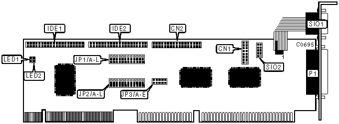
CONNECTIONS | |
|
Function |
Location |
|
16-pin game port - internal |
CN1 |
|
34-pin control cable connector - floppy drive |
CN2 |
|
40-pin IDE (AT) interface connector |
IDE1 |
|
40-pin IDE (AT) interface connector |
IDE2 |
|
2-pin connector - drive active LED |
LED1 |
|
2-pin connector - drive active LED |
LED2 |
|
25-pin parallel port - external |
P1 |
|
9-pin serial port - external |
SIO1 |
|
10-pin serial port connector - internal |
SIO2 |
|
USER CONFIGURABLE SETTINGS | |||
|
╗ Function |
Location |
Setting | |
| ╗ |
Game port enabled |
JP1/A pins 2 & 3 |
closed |
| ╗ |
Game port disabled |
JP1/A pins 1 & 2 |
closed |
| ╗ |
VL-Bus IDE (AT) interface enabled |
JP1/B pins 2 & 3 |
closed |
| ╗ |
VL-Bus IDE (AT) interface disabled |
JP1/B pins 1 & 2 |
closed |
| ╗ |
ISA-Bus IDE (AT) interface enabled |
JP1/C pins 2 & 3 |
closed |
| ╗ |
ISA-Bus IDE (AT) interface disabled |
JP1/C pins 1 & 2 |
closed |
| ╗ |
Floppy controller enabled |
JP1/D pins 2 & 3 |
closed |
| ╗ |
Floppy controller disabled |
JP1/D pins 1 & 2 |
closed |
| ╗ |
Parallel port IRQ7 select |
JP2/E pins 2 & 3 |
closed |
| ╗ |
Parallel port IRQ5 select |
JP2/E pins 1 & 2 |
closed |
|
IDE CONFIGURATION | |||||
|
╗ Primary Adapter |
JP2/A |
JP2/B |
JP2/C |
JP2/D | |
| ╗ |
VL-Bus IDE |
pins 1 & 2 |
pins 1 & 2 |
pins 1 & 2 |
pins 1 & 2 |
| ╗ |
ISA IDE |
pins 2 & 3 |
pins 2 & 3 |
pins 2 & 3 |
pins 2 & 3 |
|
Note: These settings do not apply to any IDE adapters that are already present in the system, but reflect the secondary settings on the IDE Professional VL. Pins designated are in the closed position. | |||||
|
SERIAL PORT 1 CONFIGURATION | |||
|
╗ COM |
JP1/E |
JP1/F | |
| ╗ |
COM1 (3F8h) |
pins 2 & 3 closed |
pins 2 & 3 closed |
| ╗ |
COM2 (2F8h) |
pins 2 & 3 closed |
pins 1 & 2 closed |
| ╗ |
COM3 (3E8h) |
pins 1 & 2 closed |
pins 2 & 3 closed |
| ╗ |
Disabled |
pins 1 & 2 closed |
pins 1 & 2 closed |
|
SERIAL PORT 1 INTERRUPT SELECTION | ||||||||
|
╗ IRQ |
JP2/F |
JP2/G |
JP2/H |
JP2/I |
JP2/J |
JP2/K |
JP2/L | |
| ╗ |
4 |
open |
1 & 2 |
open |
open |
open |
open |
open |
| ╗ |
2/9 |
open |
open |
open |
1 & 2 |
open |
open |
open |
| ╗ |
3 |
1 & 2 |
open |
open |
open |
open |
open |
open |
| ╗ |
5 |
open |
open |
1 & 2 |
open |
open |
open |
open |
| ╗ |
10 |
open |
open |
open |
open |
1 & 2 |
open |
open |
| ╗ |
11 |
open |
open |
open |
open |
open |
1 & 2 |
open |
| ╗ |
12 |
open |
open |
open |
open |
open |
open |
1 & 2 |
|
Note: Pins designated are in the closed position. | ||||||||
|
SERIAL PORT 2 CONFIGURATION | |||
|
╗ COM |
JP1/G |
JP1/H | |
| ╗ |
COM2 (2F8h) |
pins 2 & 3 closed |
pins 2 & 3 closed |
| ╗ |
COM1 (3F8h) |
pins 2 & 3 closed |
pins 1 & 2 closed |
| ╗ |
COM4 (2E8h) |
pins 1 & 2 closed |
pins 2 & 3 closed |
| ╗ |
Disabled |
pins 1 & 2 closed |
pins 1 & 2 closed |
|
SERIAL PORT 2 INTERRUPT SELECTION | ||||||||
|
╗ IRQ |
JP2/F |
JP2/G |
JP2/H |
JP2/I |
JP2/J |
JP2/K |
JP2/L | |
| ╗ |
3 |
2 & 3 |
open |
open |
open |
open |
open |
open |
| ╗ |
2/9 |
open |
open |
open |
2 & 3 |
open |
open |
open |
| ╗ |
4 |
open |
2 & 3 |
open |
open |
open |
open |
open |
| ╗ |
5 |
open |
open |
2 & 3 |
open |
open |
open |
open |
| ╗ |
10 |
open |
open |
open |
open |
2 & 3 |
open |
open |
| ╗ |
11 |
open |
open |
open |
open |
open |
2 & 3 |
open |
| ╗ |
12 |
open |
open |
open |
open |
open |
open |
2 & 3 |
|
Note: Pins designated are in the closed position. | ||||||||
|
PARALLEL PORT CONFIGURATION | |||
|
╗ LPT |
JP1/I |
JP1/J | |
| ╗ |
LPT1 (378h) |
pins 2 & 3 closed |
pins 2 & 3 closed |
| ╗ |
LPT2 (278h) |
pins 2 & 3 closed |
pins 1 & 2 closed |
| ╗ |
LPT3 (3BCh) |
pins 1 & 2 closed |
pins 1 & 2 closed |
| ╗ |
Disabled |
pins 1 & 2 closed |
pins 2 & 3 closed |
|
PARALLEL PORT MODE SELECTION | |||
|
╗ Mode |
JP1/K |
JP1/L | |
| ╗ |
EPP/Bi-directional |
pins 2 & 3 closed |
pins 2 & 3 closed |
| ╗ |
ECP |
pins 1 & 2 closed |
pins 1 & 2 closed |
| ╗ |
ECP & EPP |
pins 1 & 2 closed |
pins 2 & 3 closed |
| ╗ |
SPP |
pins 2 & 3 closed |
pins 1 & 2 closed |
|
PARALLEL PORT DMA CHANNEL SELECTION | ||||||
|
╗ Channel |
JP3/A |
JP3/B |
JP3/C |
JP3/D |
JP3/E | |
| ╗ |
3 |
closed |
closed |
closed |
open |
open |
| ╗ |
1 |
closed |
open |
open |
closed |
closed |
|
Note: DMA channel selection is only in ECP mode. | ||||||